

In the past, most of the charging devices of various brands used their own interfaces, which resulted in a lot of waste when the devices were replaced. Due to the popularity of USB, most products on the market transmit data through this interface, which has prompted people to want to improve the USB power supply capability. In the past, even the USB Battery Charging 1.2 (BC 1.2) method could only provide up to 7.5W (5V 1.5A), so electronic products took a long time to charge.
USB-IF (USB Implementers Forum) published the first version of the USB Power Delivery Specification Revision 1.0, Version 1.0 in 2012. Its specifications significantly increased the power supply capability to a maximum of 100W (20V 5A). As more features are added, the specification is constantly updated and has now reached USB Power Delivery Specification Revision 3.0 (subsequently referred to as PD and PD Spec).
As development becomes more and more mature, the Type-C interface gradually becomes mainstream on the market, and most products support PD. These products use
The Configuration Channel (CC) pin transmits PD communication messages and protocols and is powered through the VBUS pin. The following will start with an introduction to the Type-C architecture and gradually understand the concept of PD.
1. Source:
Monitor the CC pin voltage. When the Source detects Rd on the CC pin, indicating that the Sink is connected, the Source will output 5V on VBUS.
2. Sink:
Detect VBUS. When there is 5V, you know that the Source is connected at this time.
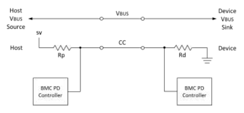
Figure 1: Schematic diagram of Type-C connection before PD communication (taken from Type-C Cable and Connector Spec)
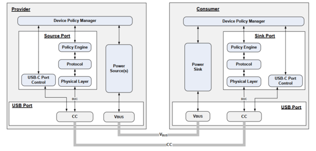
Figure 2: USB PD architecture diagram (taken from PD 3.0 Spec)
Determine how to send and respond to received PD messages based on the policy, and instruct the Protocol Layer to construct the message.
Receiver: receives the message from the PHY Layer, interprets the message and reports the information to the Policy Engine. Before making a corresponding response, it first constructs a GoodCRC message for the PHY to send back to the other party, indicating that the message has been correctly received and interpreted.
At the same time, the Protocol Layers of both devices need to calculate whether the other party has a correct response within the required time (Timer check).
If any errors are detected in the above confirmation content, the Protocol Layer of either party can initiate a Reset mechanism to reset the status:
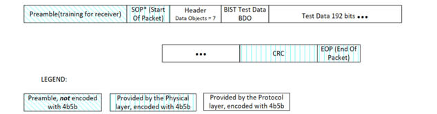
Figure 3: Schematic diagram of PD message format (taken from PD 3.0 Spec)
On the contrary, when receiving a message, the PHY must first verify the CRC of the received message, and if it is correct, the message will be sent back up to the Protocol Layer of the receiving end.
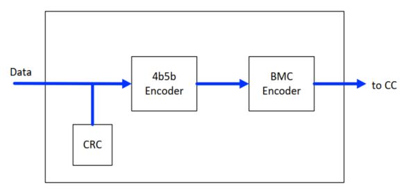
Figure 4: Schematic diagram of the message transmission process of PHY Layer (taken from PD 3.0 Spec)
The following figure takes the Source Capabilities message as an example to briefly represent the transmitter, receiver, and message transmission process in the above content:
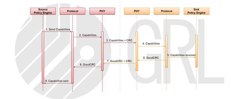
Figure 5: Source Capabilities Messages (From GRL)
From the above, it can be seen that the PD messages of the connected devices at both ends are transmitted through the same route (CC). In order to prevent both ends from transmitting messages at the same time, the Source
Protocol has a Collision Avoidance mechanism that can control the Rp setting by instructing the PHY to tell the Sink whether it can respond only to Source messages at the moment.
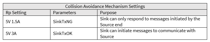
Table 3: Collision Avoidance Setting (From GRL)
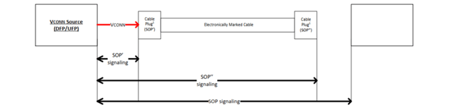
Figure 6: SOP/ SOP’/ SOP’’ communication diagram (taken from PD 3.0 Spec)
SOP messages are used between Source and Sink, SOP’ is used for messages close to the Vconn Source (responsible for supplying power to the e-Marker in the cable), and SOP’’ is used for messages with the remote e-Marker.
* Not every cable is equipped with e-Marker. If the cable supports SuperSpeed or a current greater than 3 amps, it must have eMarker according to regulations
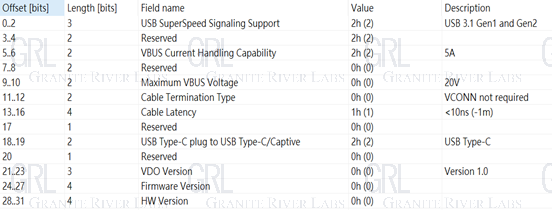
Figure 7: Interpreting Discover ID ACK content using GRL-A1 (From GRL)
Source refers to the conditions that the wire can support, and sends Source Capabilities to Sink to indicate the current power supply capability. Sink will select among them according to needs and return a Request to Source to request the current required voltage and current. Source will reply after receiving it and confirming that it can supply power under this condition. Accept, and send PS RDY after the status is ready. At this point, the Explicit PD Contract step is completed. After this, both parties can re-agree on a new PD contract depending on the situation.
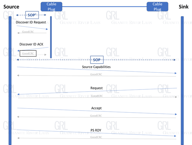
Figure 8: Explicit PD Contract process diagram (From GRL)
* To comply with international safety standards, power supply capacity is limited to an upper limit of 100 watts and a maximum current of 5 amps.
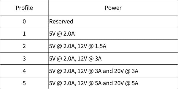
Table 1: PD 1.0 recommended power supply specifications (taken from PD 1.0 Spec)
Taking 36W as an example, you need to set the power supply capabilities of 5V 3A, 9V 3A, 15V 2.4A combination. This condition will be in Source Capabilities.
The PDO (Power Data Object) field is listed.
Each product can be added with other combinations outside the table according to needs, with a limit of no more than 7 groups.
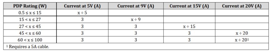
Table 2: PD 2.0 power supply specifications (taken from PD 2.0 Spec)
*After August 2020, USB-IF has terminated the certification of all products that only support PD 2.0.
In order to distinguish between the existing modes of PD 2.0 and the new PPS mode of PD 3.0, PDO can be divided into:
(1) Fixed Supply PDO (usually referred to as Fixed PDO), refers to the mode of fixed voltage output
(2) Augmented PDO (usually referred to as APDO), which means that in PPS mode, the voltage can adjust the output within a certain range
Taking 36W as an example, if the product wants to support PPS (Optional), it needs to include:
(1) Fixed PDO: 5V@3A, 9V@3A, 15V@2.4A
(2) APDO: 3.3V ~ 11V (9V Prog)@3A, 3.3~16V (15V Prog)@2.4A
Because the 5V Prog is already included in the 9V Prog specifications, you can choose not to list it separately unless the two sets of APDO currents have different settings.
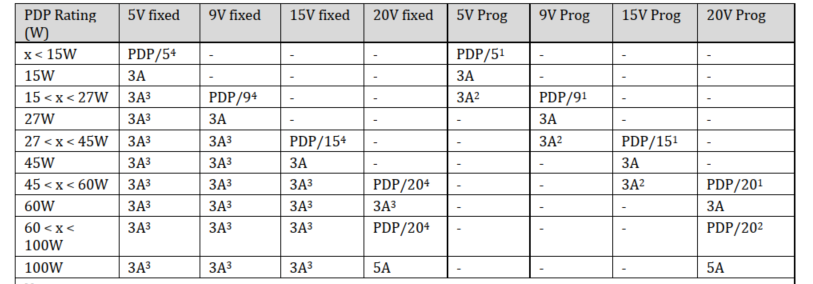
Table 3: PD 3.0 power supply specifications (taken from PD 3.0 Spec)
USB-IF (USB Implementers Forum) published the first version of the USB Power Delivery Specification Revision 1.0, Version 1.0 in 2012. Its specifications significantly increased the power supply capability to a maximum of 100W (20V 5A). As more features are added, the specification is constantly updated and has now reached USB Power Delivery Specification Revision 3.0 (subsequently referred to as PD and PD Spec).
As development becomes more and more mature, the Type-C interface gradually becomes mainstream on the market, and most products support PD. These products use
The Configuration Channel (CC) pin transmits PD communication messages and protocols and is powered through the VBUS pin. The following will start with an introduction to the Type-C architecture and gradually understand the concept of PD.
Type-C architecture (Source/Sink Detection)
Power roles are distinguished based on the power supply end and the power consumption end, which can be broadly divided into the following three types:| Power Role | Definition |
| Source | For the power supply end with power supply capability, Rp is set on the CC pin |
| Sink | Rd is set on the CC pin of the power consumption end |
| DRP | To simultaneously enable Source and Sink, both Rp and Rd should be set on the CC pin |
Table 1. Power Roles
Both ends of the connection detect whether a suitable device is connected through CC and VBUS:1. Source:
Monitor the CC pin voltage. When the Source detects Rd on the CC pin, indicating that the Sink is connected, the Source will output 5V on VBUS.
2. Sink:
Detect VBUS. When there is 5V, you know that the Source is connected at this time.
Figure 1: Schematic diagram of Type-C connection before PD communication (taken from Type-C Cable and Connector Spec)
PD architecture
Taking the Source side as an example, the Device Policy Manager is mainly responsible for monitoring the overall usage of the device. Its work includes: controlling the Power Source and USB-C Port Control modules, and working with the Policy Engine to adjust power distribution. Each port is assigned to The device protocol to which the resource is connected. USB-C Control controls the Source/Sink Detection part mentioned in the previous section. After that, the PD behavior is controlled by the three parts of Physical Layer (PHY Layer), Protocol, and Policy Engine. Finally, the Power Source supplies power to the other party through VBUS.Figure 2: USB PD architecture diagram (taken from PD 3.0 Spec)
- Policy Engine
Determine how to send and respond to received PD messages based on the policy, and instruct the Protocol Layer to construct the message.
- Protocol Layer
Receiver: receives the message from the PHY Layer, interprets the message and reports the information to the Policy Engine. Before making a corresponding response, it first constructs a GoodCRC message for the PHY to send back to the other party, indicating that the message has been correctly received and interpreted.
At the same time, the Protocol Layers of both devices need to calculate whether the other party has a correct response within the required time (Timer check).
If any errors are detected in the above confirmation content, the Protocol Layer of either party can initiate a Reset mechanism to reset the status:
| Reset Type | Purpose |
| Soft Reset | Protocol Layer reset (including timer, counters and states). Does not affect the agreed Power role, Data role and the agreed Voltage and Current before Reset. |
| Hard Reset | Will be used if Soft Reset cannot resolve the current error. Except for the Power role, all the PD protocols are restarted. In this process, the Source end will temporarily turn off the VBUS voltage to 0V, then turn it on until 5V and reconnect with the Sink protocol. |
| Cable Reset | Only the DFP on the Host end can initiate a Cable Reset to reset communication with the cables. |
| Data Reset | Reset the USB data device. After a reset, devices at both ends will not be in Alternate Mode. |
Table 2. Reset Types
- PHYLayer
Figure 3: Schematic diagram of PD message format (taken from PD 3.0 Spec)
On the contrary, when receiving a message, the PHY must first verify the CRC of the received message, and if it is correct, the message will be sent back up to the Protocol Layer of the receiving end.
Figure 4: Schematic diagram of the message transmission process of PHY Layer (taken from PD 3.0 Spec)
The following figure takes the Source Capabilities message as an example to briefly represent the transmitter, receiver, and message transmission process in the above content:
Figure 5: Source Capabilities Messages (From GRL)
From the above, it can be seen that the PD messages of the connected devices at both ends are transmitted through the same route (CC). In order to prevent both ends from transmitting messages at the same time, the Source
Protocol has a Collision Avoidance mechanism that can control the Rp setting by instructing the PHY to tell the Sink whether it can respond only to Source messages at the moment.
Table 3: Collision Avoidance Setting (From GRL)
PD protocol
1. SOP* Communication
Before understanding how to communicate, first understand that the objects to which PD messages are transmitted can be divided into three types – SOP, SOP’, and SOP’’.Figure 6: SOP/ SOP’/ SOP’’ communication diagram (taken from PD 3.0 Spec)
SOP messages are used between Source and Sink, SOP’ is used for messages close to the Vconn Source (responsible for supplying power to the e-Marker in the cable), and SOP’’ is used for messages with the remote e-Marker.
* Not every cable is equipped with e-Marker. If the cable supports SuperSpeed or a current greater than 3 amps, it must have eMarker according to regulations
2. Explicit PD Contract
The Source/Sink power supply protocol will be limited by the conditions of the intermediate wire. For example, if the source current can supply up to 5A, but the wire used can only withstand a maximum current of 3A, then the source cannot agree with the Sink on the 5A condition. Usually the Source will first send a Discover ID Request using SOP’, and then read the wire information through the Discover ID ACK returned by e-Marker.Figure 7: Interpreting Discover ID ACK content using GRL-A1 (From GRL)
Source refers to the conditions that the wire can support, and sends Source Capabilities to Sink to indicate the current power supply capability. Sink will select among them according to needs and return a Request to Source to request the current required voltage and current. Source will reply after receiving it and confirming that it can supply power under this condition. Accept, and send PS RDY after the status is ready. At this point, the Explicit PD Contract step is completed. After this, both parties can re-agree on a new PD contract depending on the situation.
Figure 8: Explicit PD Contract process diagram (From GRL)
Source Capabilities
For the specifications of Source Capabilities, the PD specification has relevant chapters describing the rules. The following is a summary of the specifications from PD 1.0 to PD 3.0:- USB PD 1.0
* To comply with international safety standards, power supply capacity is limited to an upper limit of 100 watts and a maximum current of 5 amps.
Table 1: PD 1.0 recommended power supply specifications (taken from PD 1.0 Spec)
- USB PD 2.0
Taking 36W as an example, you need to set the power supply capabilities of 5V 3A, 9V 3A, 15V 2.4A combination. This condition will be in Source Capabilities.
The PDO (Power Data Object) field is listed.
Each product can be added with other combinations outside the table according to needs, with a limit of no more than 7 groups.
Table 2: PD 2.0 power supply specifications (taken from PD 2.0 Spec)
*After August 2020, USB-IF has terminated the certification of all products that only support PD 2.0.
- USB PD 3.0
In order to distinguish between the existing modes of PD 2.0 and the new PPS mode of PD 3.0, PDO can be divided into:
(1) Fixed Supply PDO (usually referred to as Fixed PDO), refers to the mode of fixed voltage output
(2) Augmented PDO (usually referred to as APDO), which means that in PPS mode, the voltage can adjust the output within a certain range
Taking 36W as an example, if the product wants to support PPS (Optional), it needs to include:
(1) Fixed PDO: 5V@3A, 9V@3A, 15V@2.4A
(2) APDO: 3.3V ~ 11V (9V Prog)@3A, 3.3~16V (15V Prog)@2.4A
Because the 5V Prog is already included in the 9V Prog specifications, you can choose not to list it separately unless the two sets of APDO currents have different settings.
Table 3: PD 3.0 power supply specifications (taken from PD 3.0 Spec)
References
- USB Type-C® Cable and Connector Specification Revision 2.0
- USB Power Delivery Specification Revision 1.0 Version 1.2
- USB Power Delivery Specification Revision 2.0 Version 1.3
- USB Power Delivery Specification Revision 3.0 Version 2.0